The Juggernaut was introduced at the '99 Nuremberg Toy Fair (Feb 4-10, 1999). You can read about it here. However, Tamiya USA decided to pull the truck off the market due to drivetrain problems. Your local market condition may be different.
My juggernaut was purchased on 5/12/99. Assembly started 5/13/99. Truck was sold on 9/28/03.
Document updated 8/18/99.
Pictures
I took some pictures of the contents because I wanted to compare it to the Clod and the Bruiser/Mountaineer. Even more pictures at the end of this document on aluminum suspension links and chassis braces.
Contents
inside the box
The various pieces laid out on the floor
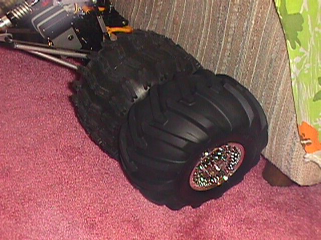
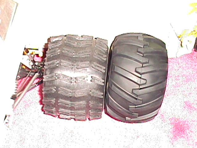
Tires, compared to ProLine Giant Traction on my
C4
Another shot of the tires
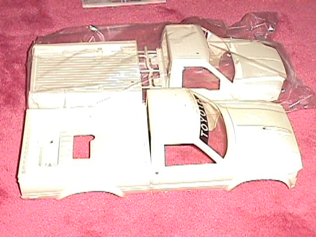
The body, compared to the Mountaineer
more pictures of the Juggernaut, during assembly
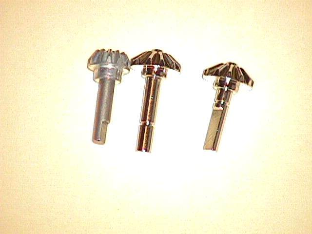
Bevel
shafts, vs Bruiser
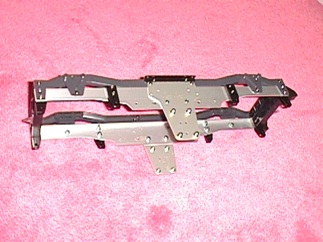
Bare frame Note incorrectly
mounted leaf spring mounts, which should be inside the frame.
Bare frame, next to my C4
(a Clodzilla 4). Partially visible is the 1/14 Mercedes 1838LS.
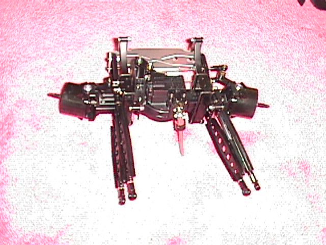
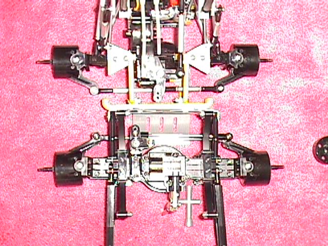
Complete axle assembly
Axle, compared to a Clod
axle. They are about the same width.
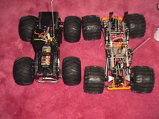
Chassis, top view, next
to my C4. Note how much bigger the C4 is.
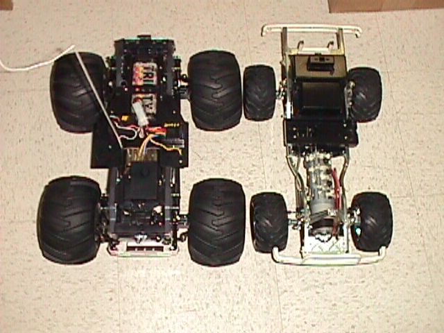
Chassis, top view,
next to a bare Bruiser chassis. The Bruiser is puny in comparison.
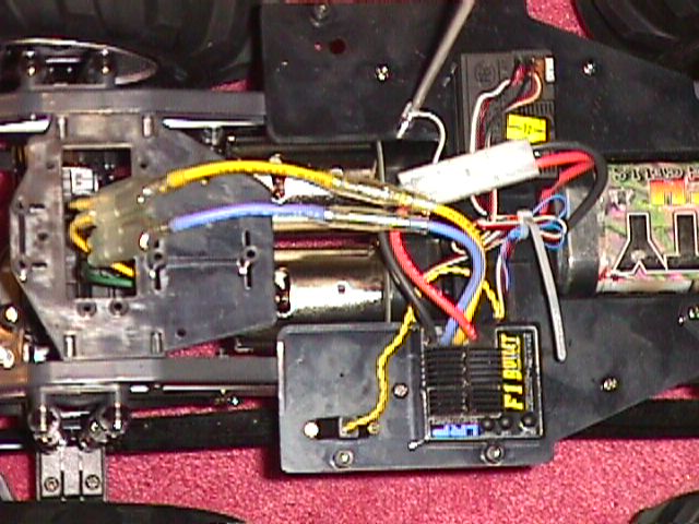
Mechanism
deck The "4x4x4" houses the mechanical speed control
(MSC) and the throttle servo.
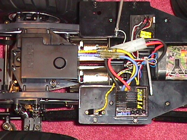
Mechanism deck, with MSC cover
removed. I kept the cover and the servo bracket, although they are no longer
necessary. The chassis looks more 'finished' with it. You can see the motor
y-cable I made.
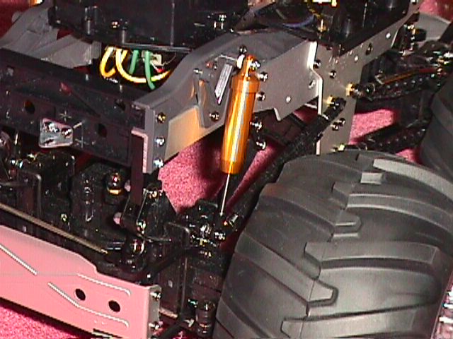
Oil Shocks, Duratrax w/o
spring.
The Juggernaut, after 1.5 hours runtime
The
paintjob Why you might not want to paint/decal yours
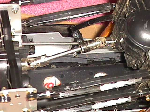
Drivetrain closeup
Bevel gears
Metal chips from bevel
gears
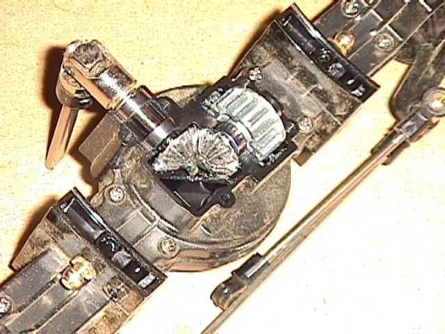
Diff
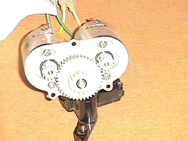
Motors and spur gear
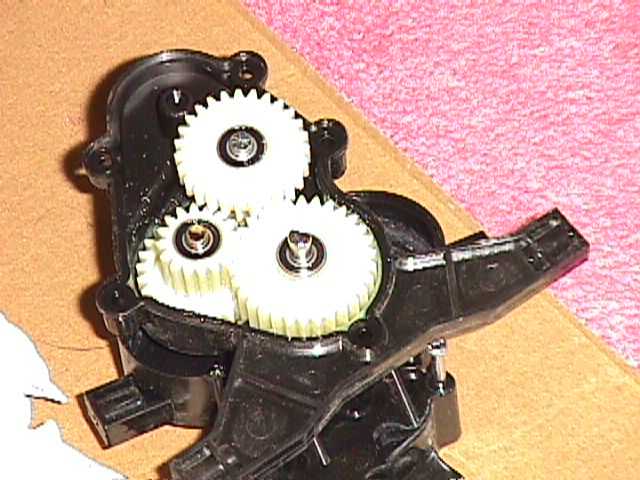
Transfer case
The box weighs approximately 14 lbs according to my bathroom scale.
Bearings
First thing, I needed to determine the bearing requirements. This kit, like the Clod, comes from the factory with 4 ball bearings (1150). These are what's required to retrofit the rest.
850, 2
1150, 10
1260, 16
Size in mm, eg 850 = 8mm o.d. x 5mm i.d.
You can basically start with a Clod bearing set (850x4, 1260x16), then add a 10-pack of 1150's.
Parts interchangeability
The axle shafts, hub shafts, hubs and hub carriers are standard Clod components. Since they use the same hubs, the wheels are interchangeable. The servo saver/steering bellcrank assembly is the same as the Clod. The bumper/skidplate are about them same width as the Clod bumpers, and can be bolted on with a bit of modification, once you modify the Clod bumper mounts. I plan to do this soon.
Not sure about the Clod, but the Juggernaut rollbar does not have the same mounting points as the Mountaineer.
The bevel shafts are not interchangeable with the bruiser.
The u-joints will work on the bruiser, even though they have different part numbers. Note that Juggernaut u-joints (as well as the one attached to the propeller shaft) have a 'step' machined (turned down) on the end so it sits recessed into the transfer case and axle, probably to keep the dirt out. Dimension-wise, the two u-joints are the same, except for a 1.5mm long section of the Juggernaut u-joint, where the diameter is reduced from 12mm to 9mm. This means that you can use the bruiser u-joint, but you'll have to either (a) turn down the diameter yourself, or (b) use as-is and not worry about the recess.
Observations
The ladder bars (suspension links) are plastic. The differentials are not the same unit as those found in their 1/14 tractors (similar, but much beefier). The steering servo is mounted in a similar manner to their touring cars - 2 nylon blocks that screw onto the chassis sideplate, for the servo mounting tabs. There's also an aluminum servo 'output shaft support'.
Although I did not use the stock mechanical speed control, it appears that the motors are wired in parallel.
The standard coilovers have a length of 3.5", eyelet to eyelet.
Building the kit
Complete chassis + electronics took about 8 hours. I broke my time down to 2 hour chunks. This is one of the most time consuming kits I've encountered.
Take care assembling your kit. I can see that maintenance will be a chore so a little foresight will go a long way.
My Setup
Futaba 2PCKA Tx/Rx
Futaba S9402 hi-torque/hi-speed servo
LRP F1 Bullet ESC, motors wired in parallel
Trinity Ex-Tech 2000 battery
Full ball bearings
Everything else is stock
Test Run
I only had time for one indoor test run (w/o body), using a fully-charged 2000mAH battery.
The runtime wasn't bad (I didn't time it, but it ran for about 10 minutes?) and the climbing/pulling power seems comparable to my C4 over the same obstables. No complaints about the steering, except some trimming I might have to do with the tierods. I think the turning circle beats my C4, partially due to the shorter wheelbase. I can do figure 8's and circles in my living room.
It has a tendency to lift one of its front wheels if you nail the throttle (torque reaction). Give it enough throttle, and you can pop a small wheelie. Also, if it is stuck on an obstacle and you try to power it up, every once in a while I hear snapping or popping sounds (drive bevels slipping). (Note: Bruisers do not exhibit these tendencies). The suspension swing arms have a tendency to twist, so maybe it is the tires hitting the swing arms at full luck. I definitely want to put my lathe to good use, and make a set of swing arms out of aluminum rods, but first I need to get a 3mm tap. The chassis is begging for a better suspension setup.
The stock suspension is very stiff, and there's zero damping. Needless to say, the ride is very bouncy. I can try mounting a set of Duratrax 4" oil shocks (one each corner, w/o springs) later and see if it helps (note: already done. See below). It has about 1 - 1.5 inches of travel (the standard lift one wheel while keeping the other 3 on the ground test). The C4, on the other hand, can rest one of its tires on the Juggernaut's tire, and still have quite a bit of travel left...
The LRP F1 Bullet barely gets warm, even if I intentionally load the motors. It certainly runs cooler than the Super Rooster.
So far, I like it because everything goes together as a system and assembles perfectly. The C4 on the other hand is an ongoing project because almost everything needs to be custom fitted. Peformance-wise it is another story. One of these days I'll take both out for some rock crawling.
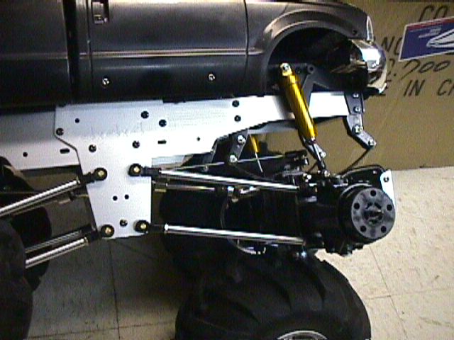
Suspension
I replaced the stock coilovers with Duratrax 4" oil shocks I had on hand. The length is about perfect, and installation is trivial. I filled the shocks with Tamiya's purple silicone oil (heaviest). Initially I tried the shocks with the coil springs in place but I thought there wasn't enough damping (I'd have to find appropriate pistons) so I removed the springs. The damping is about right if I use only the leaf springs. I installed an o-ring on each shock shaft so I can get a good indication of suspension travel. It bottoms out if I drop the truck (chassis, with battery etc) from about 12 inches. Since the body will add some weight I might have to up the damping some more and use auxiliary springs.
Without serious work, I doubt you'll be able to sail the truck 12 feet off the ground and have it land intact.
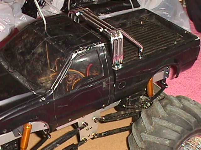
Painting and detailing the body
Body painted black using standard spray paint. I bought the cheapest black enamel spray at Home Depot ($1.xx). I did not sand the body or use any primer. All I did was wash the body with soap and let it dry before spraying (outdoors). The paintjob was actually very decent after I spent some time wet sanding it. Unfortunately, all that labor went to waste on the first outing. The truck flips fairly easily, so in addition to scratched paint/window from running thru the bushes in the backyard, the body also have a fair amount of road rash.
If I had to do it over again, I'd leave the body unpainted. Knowing now that the body/paintjob will get thrashed in the first outing, I could've saved a bunch of time and energy preparing, painting, waiting days for it to cure, wet sanding and compounding it. Being a perfectionist has its disadvantages, I guess.
Performance
Jumping from a moderate height (9"?) the suspension as I had set up works fairly well. The tires also act as decent shock absorbers.
As mentioned before, the turning radius is incredibly tight.
The truck handled most reasonable obstacles found in my backyard, lawn, and street. Occasionally it gets stuck if it straddles a brick lengthwise (limited clearance under diff). The tires provide a lot of traction.
Reasonably well-kept lawns do not slow down the truck much.
All in all, it is a fun truck. I don't regret buying it and hopefully the gearbox popping noise will get taken care of. Tamiya is aware of it and is investigating.
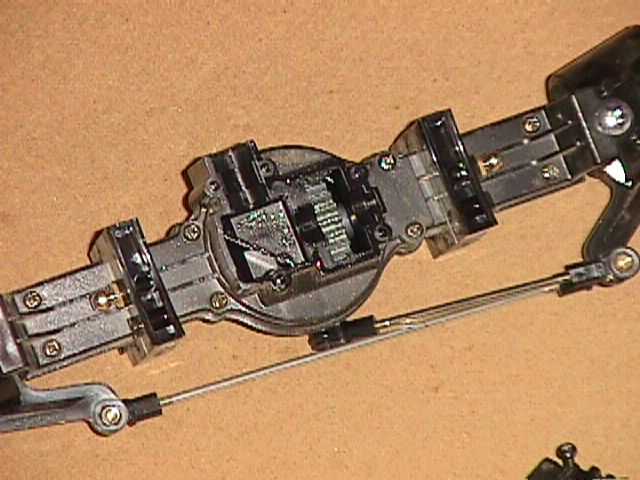
Juggernaut's Achilles Heel - the bevel gears
After several pack's worth of runtime (about 1.5 hours) I decided it's time to do a teardown and see how the gears held up. I also wanted to investigate what's causing the infamous popping sounds many (most?) Juggernaut owners hear. Please refer to links at the top of page for photos.
It is the bevel gears.
The brass wheel hubs were perfect. No slippage there.
As expected, the bevel gears (there are two in each axle) had unevenly worn spots. This can be explained because when the popping noise occurs, usually the truck is experiencing heavy throttle and/or resistance to movement. The bevel gears are slipping (skipping a tooth). There are also bits of metal inside the bevel shaft pocket and gear cover, from the bevels themselves and the plating flaking off.
I didn't do much to fix it. All I did was re-orient the mating surfaces of the bevels, so they have a fresh spot to wear down. Not much of a fix - I'm just going to deal with it. Of course, I spoke to Tamiya. They (both US and Japan) are investigating the problem.
My conclusion is supported by the fact that there are virtually no wear in any of the other gears, as can be seen in the photos (this document does not follow the actual disassembly sequence). The drive gear and the diff gear assembly have zero wear and operation is still smooth as silk.
I also inspected the gearbox/transfer case. No wear on the spur gear despite there are two motors driving it, and no wear on any of the gearbox gears.
Except for the drive bevels, this truck's drivetrain is far stronger than I had expected.
Modifications and Ideas
I built it stock (with full bearings) so I can play around with it for a while then decide on what to modify.
Steering
Since the steering bellcranks appear to be identical to the Clod's, you can
probably use ESP's bellcrank and go with a Kimbrough servo saver instead. Due
to the transmission, there isn't enough room on the opposite chassis sideplate
for a symmetrical dual servo setup. I'm sure with some modifications, dual servo
setup can be implemented, but that will require a beefier ESC such as the Novak
Super Rooster to handle the current drain of 2 servos/2 motors.
Chassis
The swing arms (suspension links) can be replaced with aluminum rods and threaded
studs, and relocate the lower rods to mount on the bottom of the chassis (once
I build another aluminum brace). Once you have the axle movement under control,
you can then ditch the stock leaf springs and replace with a nice cantilever
or even coilover setup. Extending the wheelbase won't be a problem (to some
extent) because I already have similar driveshafts for the bruiser.
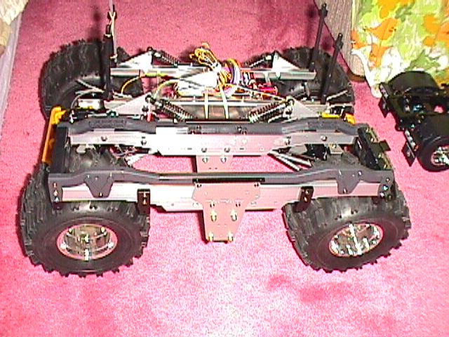
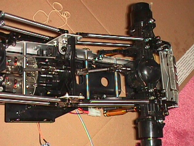
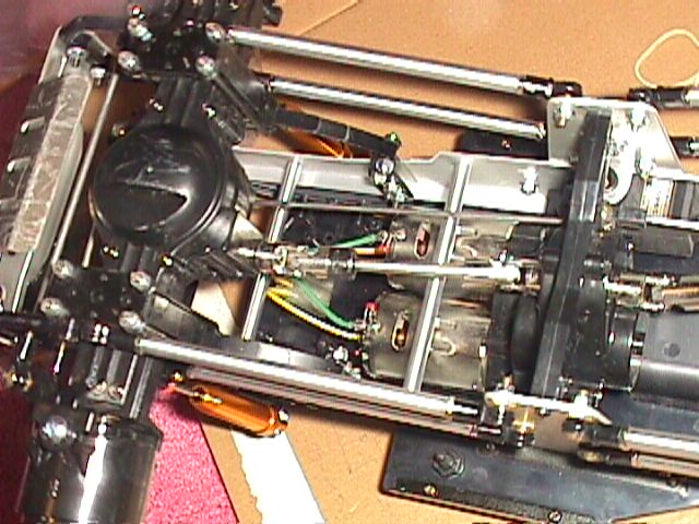
Phase 1 - Suspension Links and Chassis Braces
I made my own 1/4" round aluminum suspension links. My links are stock length and are threaded for the stock 3mm threaded shafts for simplicity. I have a small metalcutting lathe, and it is a fairly simple but time consuming job to make 8 links. They are cut from 1/4" round aluminum rods (about $1.15/ft), faced to the correct length (about 9.93cm), drilled and tapped for 3mm x 0.5 threads, and finally polished with emery cloth. There is an extra drilling step I had to do, since Tamiya's threaded shafts aren't threaded the whole length. I had to drill out the first 3/16" of each end to clear a 3mm rod. The whole job took maybe 3 hours.
I made 4 Upper Chassis Braces, 9.85cm in length. They are made the same way as the suspension links. These only took 1 hour to make since I've had plenty of practice from making the suspension links.
Brace #1 & 4 are bolted to where the shock towers go thru the chassis, and #2 & 3 to existing holes closer to the center of the chassis, under the motors and battery tray.
Here are two pictures: Picture1 Picture2
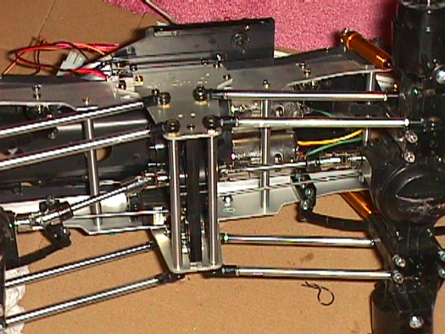
Later on, I made 2 Lower Chassis Braces, 10.2 cm in length. They are bolted to the lower suspension link ball ends. They stiffen up that portion of the chassis a bit, which is always nice. The assembly can be made stiffer if I connected the two brace rods together.
I might not make servo pushrods because I may have to re-engineer that portion if I extend the wheelbase. I might use bicycle brake cables instead.
Steering linkages will be just as easy to make.
New Era Models sells similar upgrades, but why buy when I can make them?
Phase 2 - Long Wheelbase Links
This might be a bit more complicated, because your steering angle will change more drastically as the suspension moves up/down. Extending the driveshafts isn't a problem. Standard off-the-shelf Tamiya components (Propeller shaft, part # 4135043: 108mm extended, 101mm collapsed). Juggernaut's driveshafts are 91mm extended, 84mm collapsed. That's probably good for maybe another 1 -1 1/4" of wheelbase. You can also use Mountaineer long driveshafts (Tamiya #4135011, discontinued) IF you can find them. Remember, you read it here first.
The leaf springs will be ditched in favor of normal coilovers. The lower suspension links will be relocated to better control lateral axle movements. It has not been decided whether I will use cantilevers.
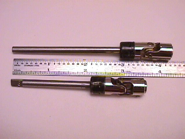
Progress:
7/22/99: I began by turning down the end of the propeller shaft u-joint, so it mates into the recess on the axle. Here's a comparison of the shafts. I've mentioned the u-joint differences earlier so I won't repeat it here. I only turned down to 9mm diameter about 0.5mm into the face. The setscrew location is different, so cutting too far in will possibly weaken the setscrew surrounding area. Of course, one can re-drill the setscrew hole, but I chose not to.
12/12/2002: I basically got sidetracked by various other things going on in my life, and lost interest in this project. I stopped playing around with this truck ever since I installed Juggernaut 2 upgrade parts (courtesy of Tamiya). That solved the original drivetrain issues. I still have this truck.
Main Page This page is part of a frameset. If you found it via a search engine, please visit the whole site for additional details!