Clodzilla 4 Pro Race
Kit Chassis
Clodbuster/Clodzilla IV Monster Truck buildup
Quick Index
Clodzilla Buildup
Gearboxes
Bearings
Custom Fabrications and Modifications
Axle Installation
Servos
ESCs
In Retrospect
My Setup
Misc Info
Pictures
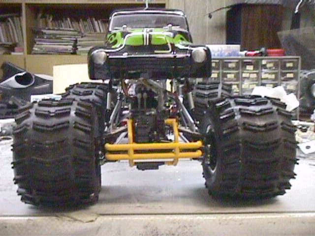
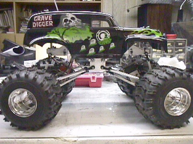
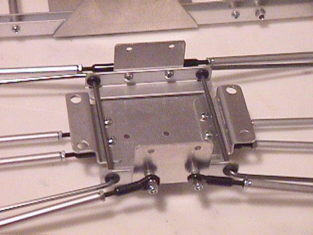
Front
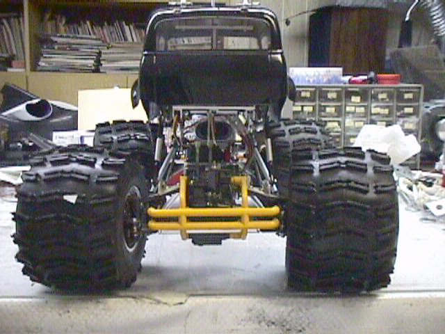
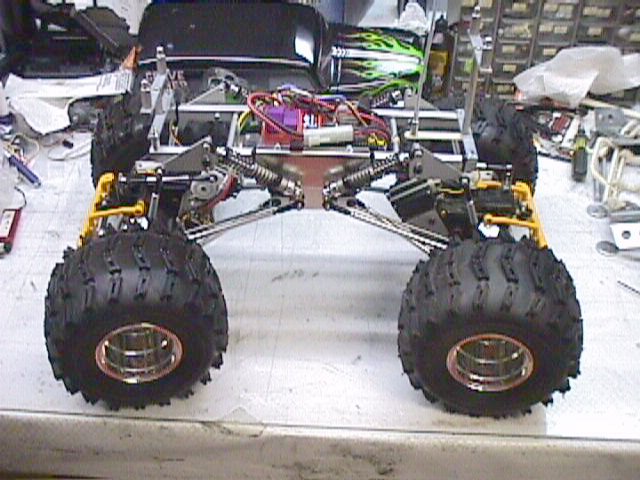
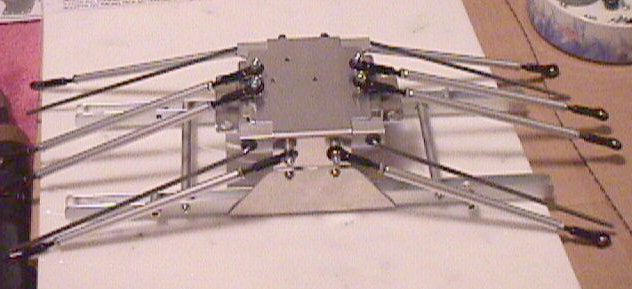
Rear
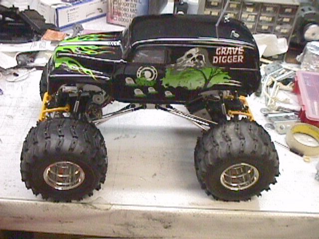
Left
Another Left
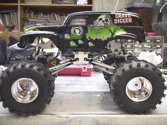
Right
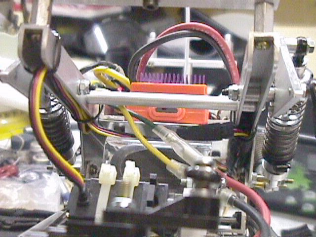
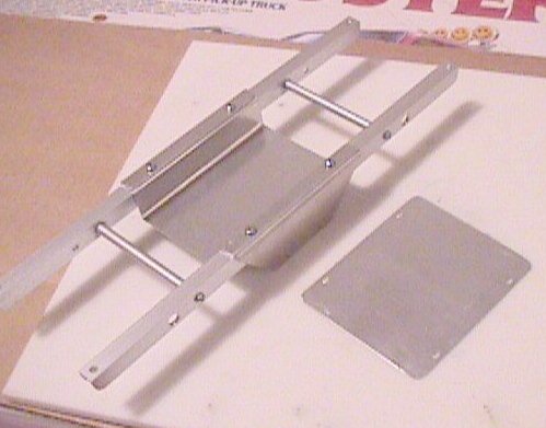
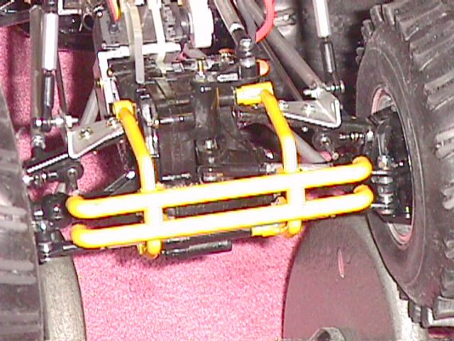
Ladder frame showing wiring
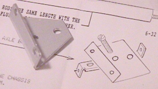
closeup
Chassis
More picture links in text below.
Clodzilla buildup
Tamiya 58065 Clodbuster kit
ESP Hobbies Clodzilla IV Pro Race Kit, ESP048
This project started 1/9/99. I finally finished it on 7/18/99. It had been in rough running form (w/o body) for some time, but now at least all the major pieces are there and I can leave it alone. I'm sure there are things I can tinker with, but I'm satisfied for now.
The Parma Gravedigger body is temporary until I finish painting my other body. I got it used, and almost got rid of it. It was originally on a Bruiser, which is why it had some extra holes in it.
Begin
** Get yourself a bottle of Loctite (242 - blue) or a bag of 3mm locknuts! **
The instructions assume you're starting from a full Clodbuster kit (or new gearboxes) and a full Clodzilla IV kit. Depending on how you started off you may still benefit from these notes, as the ESP instructions are pretty horrible. However, there is a reason why assembly takes place in a certain order.
1. Build the Clodzilla 4 chassis (esp045). Some minor pains are: some screws you have to get from other ESP packages (explained in instructions) but can be a pain. ESP screwed up by shorting me one 3x10 screw, instead packing a 3x5!
I really wish ESP had written the instructions using normal fonts and mixed case characters. It is a bit hard to read.
2. I guess I jump to step #2 on the ESP instruction sheet, building the LWB multilink suspension kit (ESP032)
3. Jump to ESP047 anti-sway bar kit, so I can mount those battery stays.
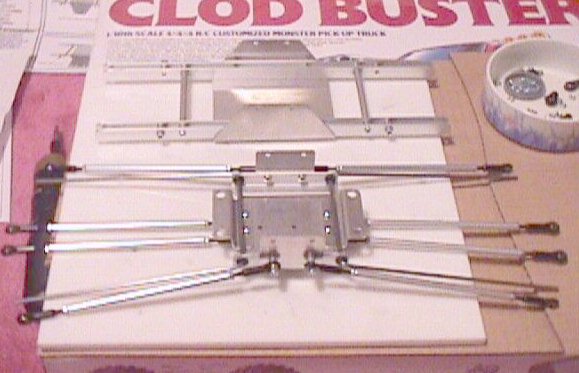
So, you’d first build the suspension rods, then build the anti-sway bar assembly. The battery stays are secured with the same 3x15mm bolts for the lower suspension links (where I used 3mm locknuts). Picture1 Picture2
Then, the anti-sway chassis mounts are mounted to the chassis brace, using the same 3x15mm bolts for the upper suspension links (again, I used 3mm locknuts). Finally, the upper chassis and lower chassis are mated together. I substituted the kit 3x10mm bolts with Tamiya 3x10mm bolt, 3mm washer, and 3mm flange nut. (qty 4 of each used). Picture
Total time spent up to now: 2 hours, 20 minutes.
1/9/99Start 6:15PM, end 9:30pm
Start 12:45am end 3:30am
Parts B7 and B11 are not required, otherwise assemble as per Tamiya instructions.
Motor: pinion to motor mounting face: 17mm
Screw bag D discarded all 20 1260 plastic bearings.
Bearings:
Axles: 4 kit-supplied 1260 tamiya bearings, 4 optional 1260 bearings. Total = 8.
Gearboxes: 4 850 and 4 1260 optional bearings. Total=8.
Knuckles (hub): 2 1260 optional bearings per knuckle. Total = 8.
Size in mm, eg 850 = 8mm o.d. x 5mm i.d.
Step 26. You can temporarily skip this step until you get to ESP Dual Steering Kit. For ESP Dual Steering, you don’t need to install the 3mm nut inside each gearbox, and B11. Don’t bother installing the motor and B7.
Do not install Tamiya brass ball connectors on steering knuckles and servo saver/bellcranks.
Now is a good time to assemble ESP Deluxe Steering Rod Kit ESP037, and Dual Servo Conversion Kit ESP040. Tamiya's instructions tell you the INSIDE distance from rod end to rod end, while ESP tells you nothing. Best way is to assemble Tamiya's, then measure the eyelet to eyelet distance and replicate on ESP's. Here are my measurements:
Tie rod (short): 75mm eyelet to eyelet
Tie rod (long): 148mm eyelet to eyelet
(add 10mm for end to end length)
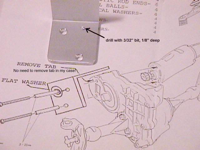
I modified the ESP servo mounts instead of modifying the gearboxes. See below.
When attaching Tamiya axle braces, instead of using kit 3x6 screw, use 3x20mm screw. You’ll use this to attach the upper suspension link. See my notes on axles.
Custom Fabrications and Modifications
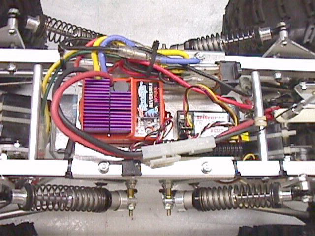
I was not particularly satisfied with the engineering (or lack thereof) of certain aspects of ESP's kit. In particular, the radio tray and battery tray.
I feel that the radio tray puts the center of gravity too high. There is also no elegant way of securing the battery to the chassis.
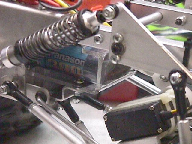
My recessed radio tray is made from sheet aluminum purchased at Home Depot. They are called "aluminum flashing" and you can find it in the aluminum siding section. It is fairly thin and easy to work with for prototyping.
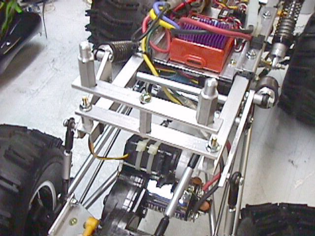
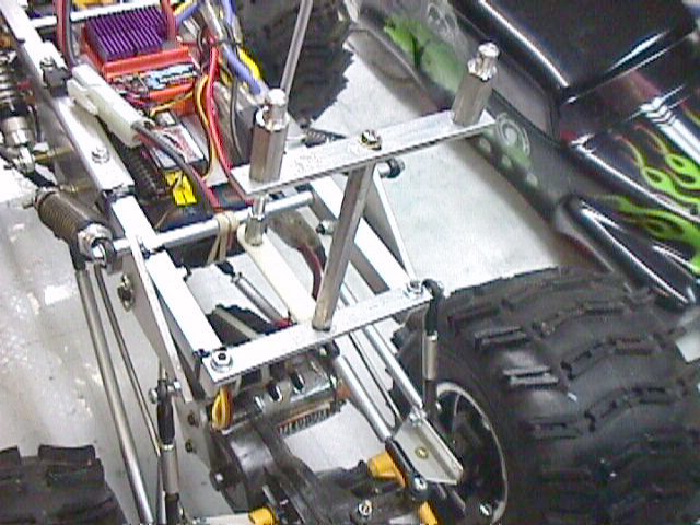
The mounts can be adjusted to fit many Tamiya pre-drilled bodies. I had some predrilled bodies around, and I did not want to drill additional holes, hence my own design. Consideration was given for crashability. I do not want to bend the ESP ladder frame, so the chassis was braced. Note that the front brace has clearance to clear servo pushrod. The mounting posts can be replaced easily if bent, or if different heights are required for different bodies.
It was made from a pre-bent plexiglass piece I found at a plastic shop. It was almost perfectly sized for a standard stick battery. The only thing I really need to do is to hold down the other end of the battery with a rubber band. Next step is to duplicate this design in aluminum, as plexiglass is too fragile (it broke already).
Notice the Trinity 3000mAh battery? On my Tekin BC112C, it takes 45 minutes to charge at 4A (no PF mode, no trickle), and the runtime is awesome. Note on 3000 mAh batteries: they get warm when they peak. You want to stop charging when the voltage stops rising so keep your eyes on the voltmeter during the last few minutes, and feel the pack (warm ok; don't let get hot). Do not let the voltage drop (over .02) because you might damage the pack.
Unscientific timing (hiking trail, 2x Trinity SpeedGem2 Sapphires, 1 outing)
3000 mAh: 15 minutes
2000 mAh: 11 minutes
1700 mAh: 7 minutes
Installing axles to the chassis
I don't think ESP gives you good instructions on axle installation. I've had to install and de-install my axles occasionally, and have come up with the following procedure:
1/12/99 start 11:30pm end 1:30am
Cantilever suspension system. It would’ve been nice if ESP included the allen wrench necessary for the cantilever bolts. It is SAE size and I had to scramble around for one.
The goal was to have dual steering as intended by the kit. Clodzilla 4 dual steering requires 2 servos connected via a y-cable. Naturally, if you use matching servos, you either have to mount one (rear servo) upside down, or find a way to electronically reverse the servo (NOT from the TX). The solution suggested by ESP is to mount the rear servo upside down. Since the rear servo uses a smaller servo saver, it can work work. In actuality, the servo saver will most probably hit the motor can (trim the servo saver to fit), and the servo rod is a bit on the short side.
I’ve gone through several different makes and models of servos.
Futaba S9402
Futaba S148
Airtronics 94102
Hitec HS303
Futaba S3003
Hitec HS605BB
I originally wanted two different servos, that rotate opposite from each other. This way, the servos can be mounted the same way. S9402, S148, HS303, S3003 all rotate the same direction. HS605BB and Airtronics 94102 rotate the opposite way. Note my 94102 is very old (15 years old?) so I can’t guarantee they are still the same these days.
There are workarounds if you want a clean installation using two identical servos. Tower sells an electronic servo reverser (look in their main catalog), or dissect the servo and reverse some wires. Do NOT just pull out the control wires (+ and -) and reversing them. You will most likely fry your servo.
In theory, you can reverse a servo by opening up the case and doing the following: desolder the motor +/- tabs from the PC board, reverse the motor (rotate 180 degrees) and solder back. Then desolder the outside two wires for the pot, cross them and solder back. This was told by various members of the R/C community, and from a Hitec technician himself (of course, this voids the warranty).
Eventually, I used Hitec HS605BB high torque servos and reversed one of them. Here's how:
For this particular servo, it is a 10-minute job because the motor and pot are actually connected with wires, and not soldered onto the PC board like some other servos encountered. YMMV.
Mount your servos to the ESP servo mount with double-sided servo mounting tape, and zip tie them down securely.
Most higher-end ESCs can handle single servo/dual motor setups fine, I've found that you MIGHT run into power problems running two servos and two motors. I've used LRP’s F1 Bullet and F1 Digital, and Novak's Super Rooster on my chassis. Try this test: Crank the steering to full lock, and hold it there while applying throttle. See if the truck goes forward immediately. LRP ESCs won't respond until you let up on the steering, while the Super Rooster worked fine. This is regardless of the make/model of servos or motors used.
I suspect this has something to do with the ESC's BEC output. LRP provides 0.5A while the Super Rooster provides 3A. So, if you encounter the same problem, try the Super Rooster.
I did notice that the Super Rooster runs a little warmer than the LRP F1 Bullet, but it isn't a big deal. The LRP works beautifully in touring cars, BTW.
In Retrospect
The Clodzilla 4 Pro Race Kit box measures 12 ½" x 11 ¼" x 2 ½", and weighs 2.2 lbs.
The Clodbuster kit box measures 26 ½" x 18 x 6 ¾", and weighs around 12 ½ lbs.
What’s the difference between Tamiya 6mm Ball connectors and ESP’s? ESP uses ¼", or 6.35mm Balls. You can connect Tamiya ball connectors to ESP’s rod ends, but there will be some play.